
Ultrasonic Spray Coating for Fuel Cell MEAs
The membrane electrode assembly is the electrochemical core of a fuel cell. Its catalyst-layer uniformity, catalyst loading, porosity and interfacial quality directly influence cell performance, durability and material utilization.
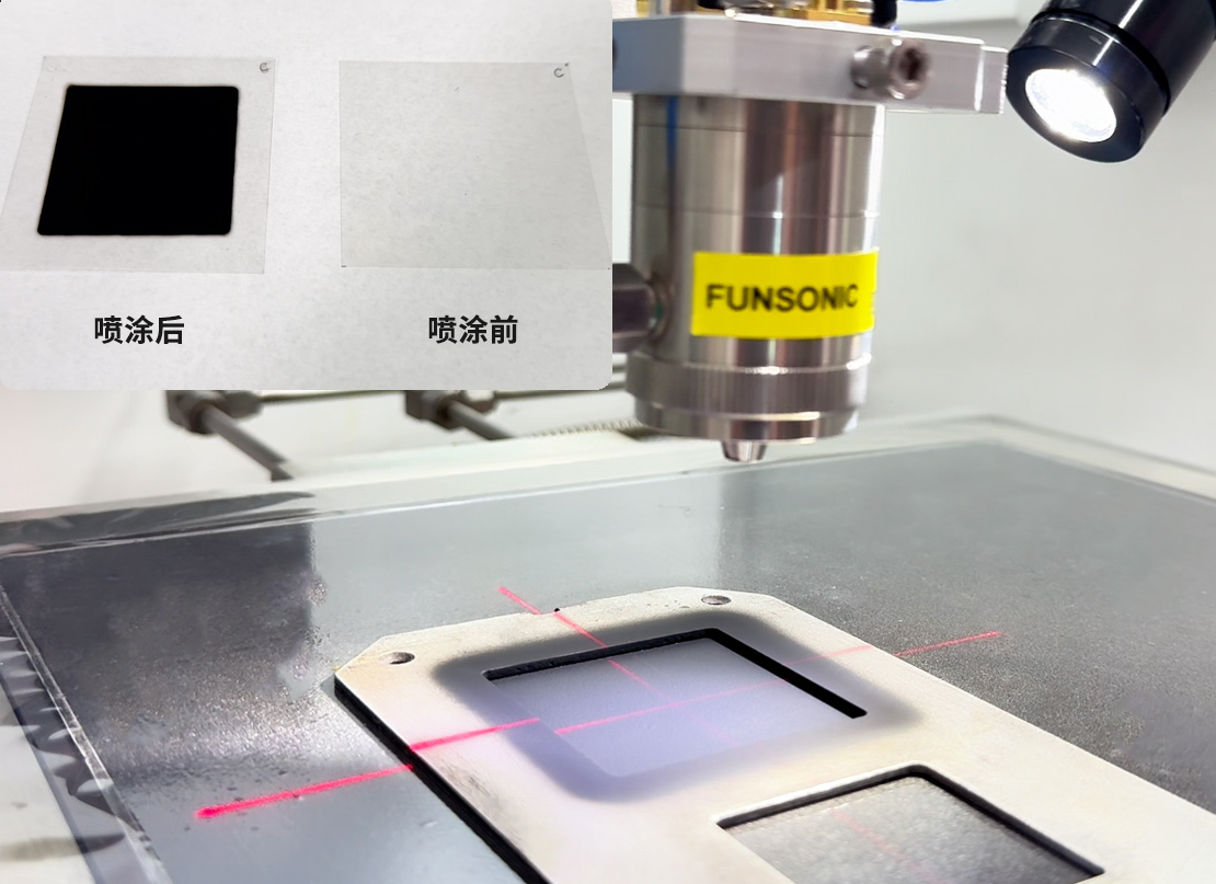
Ultrasonic spray coating provides precise atomization and controlled deposition of catalyst inks onto proton exchange membranes, gas diffusion layers and other MEA components. The process is suitable for catalyst research, electrode development, laboratory fabrication, pilot production and automated manufacturing.
Fine, low-velocity droplets help form uniform functional layers while reducing overspray and the waste of platinum-group metals and other valuable catalyst materials.
Fuel Cell MEA Coating Challenges
Fuel cell catalyst inks commonly contain catalyst particles, ionomers, water, alcohols and other solvents. Their dispersion, wetting and drying behavior can make the coating process difficult to control.
Typical challenges include:
- Non-uniform catalyst distribution
- Particle agglomeration or settling
- Inconsistent catalyst loading
- Excessive catalyst waste
- Poor adhesion between the membrane and catalyst layer
- Membrane swelling or deformation
- Cracking, pinholes and edge accumulation
- Non-uniform coating on porous gas diffusion media
- Uncontrolled drying and solvent evaporation
- Difficulty reproducing laboratory results at a larger scale
A reliable MEA coating process requires coordinated control of ink formulation, atomization, liquid flow, spray pattern, substrate temperature, coating speed and drying conditions.
How Ultrasonic Spray Coating Works
Catalyst ink is delivered to an ultrasonic spray nozzle at a precisely controlled flow rate. High-frequency vibration at the nozzle tip converts the liquid into fine droplets without requiring high liquid pressure.
Controlled shaping air directs the atomized droplets toward the membrane, gas diffusion layer or electrode substrate. A programmable motion system moves the nozzle or substrate along overlapping spray paths to achieve consistent coverage.
The required catalyst loading can be built gradually through multiple thin coating passes. This approach improves process control and helps prevent excessive wetting, local flooding and uneven drying.
Suitable Fuel Cell Technologies
Ultrasonic spray coating can support coating development for:
- Proton exchange membrane fuel cells
- Polymer electrolyte membrane fuel cells
- Direct methanol fuel cells
- Anion exchange membrane fuel cells
- Alkaline membrane fuel cells
- Reversible fuel cells
- Laboratory fuel cell test devices
- Fuel cell catalyst screening
- Hydrogen energy research and pilot production
The coating method and equipment configuration should be selected according to the catalyst ink, membrane type, electrode structure and required production capacity.
MEA Components and Coating Methods
Catalyst-Coated Membranes
Catalyst ink can be deposited directly onto one or both sides of a proton exchange or anion exchange membrane to manufacture a catalyst-coated membrane.
This method allows controlled formation of anode and cathode catalyst layers while supporting precise catalyst-loading adjustment.
Gas Diffusion Electrodes
Catalyst ink can be coated onto gas diffusion layers to produce gas diffusion electrodes. The coated electrodes can subsequently be assembled or laminated with the membrane.
Gas Diffusion Layers and Microporous Layers
Ultrasonic spraying can also be evaluated for applying carbon-based or other functional coatings onto gas diffusion media and microporous layers.
Decal and Transfer Substrates
Catalyst layers may be deposited onto suitable transfer films before being transferred to a membrane through a separate lamination or hot-pressing process.
Coatable Materials and Substrates
Typical coating targets include:
- Proton exchange membranes
- Anion exchange membranes
- Catalyst-coated membranes
- Gas diffusion layers
- Gas diffusion electrodes
- Carbon paper
- Carbon cloth
- Microporous layers
- Decal and transfer films
- Porous electrode substrates
- Laboratory test coupons
Typical coating liquids may include platinum-based catalyst inks, non-platinum catalyst formulations, ionomer-containing inks, carbon dispersions and other functional materials.
Material compatibility and atomization performance should be confirmed through sample testing.
Key Benefits
- Fine and uniform catalyst-ink atomization
- Precise catalyst-loading control
- Reduced overspray and catalyst waste
- Efficient use of platinum-group metals
- Repeatable multi-pass deposition
- Uniform coverage of membranes and porous substrates
- Programmable spray paths and coating areas
- Suitable for low liquid flow rates
- Compatible with heated substrate platforms
- Scalable from laboratory research to automated production
- Customizable for CCM, GDE and GDL coating processes
Typical MEA Coating Process
A typical fuel cell MEA coating process includes:
- Prepare and disperse the catalyst ink.
- Filter the ink when required by the nozzle and particle characteristics.
- Secure the membrane, GDL or transfer substrate on the coating platform.
- Set the liquid flow rate, ultrasonic power and shaping-air pressure.
- Adjust the nozzle distance and substrate temperature.
- Program the coating area, movement speed and spray-path overlap.
- Apply multiple thin coating passes.
- Control inter-pass drying to prevent flooding or membrane deformation.
- Dry, laminate or hot-press the coated components as required.
- Measure catalyst loading, coating weight and surface uniformity.
- Assemble and test the completed MEA.
Final process conditions should be established through testing because different membranes, catalyst inks and electrode structures behave differently during coating and drying.
Important Process Parameters
The coating result is influenced by:
- Catalyst type
- Catalyst particle size
- Ionomer type and content
- Solvent composition
- Solid content
- Ink viscosity
- Dispersion stability
- Liquid flow rate
- Ultrasonic nozzle frequency and power
- Shaping-air pressure
- Nozzle-to-substrate distance
- Nozzle movement speed
- Spray-path overlap
- Number of coating passes
- Substrate temperature
- Inter-pass drying
- Target catalyst loading
- Ambient temperature and humidity
These variables should be optimized as one complete process rather than adjusted independently.
Recommended System Configuration
A typical ultrasonic coating system for fuel cell MEA development may include:
- Ultrasonic spray nozzle
- Digital ultrasonic generator
- Precision syringe pump or pressure-based liquid delivery
- Programmable XY or XYZ motion platform
- Adjustable shaping-air module
- Vacuum substrate-holding platform
- Heated coating platform
- Exhaust or fume-extraction enclosure
- Catalyst ink stirring or circulation system
- Automatic nozzle-cleaning function
- Vision alignment system
- Process recipe and parameter control
Compact laboratory systems are suitable for catalyst screening and MEA development. Larger platforms can be configured for pilot production, automated coating or continuous substrate handling.
Sample Testing Is Recommended
Catalyst inks vary significantly in composition, viscosity, particle size, stability and atomization behavior. Membranes and porous substrates also respond differently to wetting, heating and drying.
Sample testing is recommended before final equipment selection.
For evaluation, please provide:
- Fuel cell type
- Catalyst material
- Ionomer type
- Solvent composition
- Ink solid content
- Viscosity
- Particle size
- Target catalyst loading
- Substrate material
- Substrate dimensions
- Required coating area
- Laboratory or production capacity
- Current coating method
- Photos or drawings of the component
Based on this information, FUNSONIC can recommend a suitable nozzle, liquid delivery method, motion platform and temperature-control configuration.
Frequently Asked Questions
Can ultrasonic spraying be used to manufacture catalyst-coated membranes?
Yes. Catalyst ink can be deposited directly onto suitable fuel cell membranes to form anode or cathode catalyst layers. Ink formulation, membrane fixation, substrate temperature and drying conditions must be optimized to control membrane swelling and coating uniformity.
Can the system produce gas diffusion electrodes?
Yes. Catalyst inks can be coated onto carbon paper, carbon cloth and other compatible gas diffusion media. Sample testing helps determine the appropriate wetting, penetration and catalyst distribution.
How is catalyst loading controlled?
Catalyst loading is controlled through ink concentration, liquid flow rate, coating area, nozzle movement speed and the number of coating passes. Gravimetric measurement or another suitable analytical method should be used during process development.
Can different catalyst loadings be applied to the anode and cathode?
Yes. Separate coating recipes can be created for each side of the membrane or for different electrode substrates. Flow rate, coating passes and spray paths can be adjusted independently.
Can the system handle catalyst inks containing particles?
Many particle-containing catalyst inks can be atomized, provided that particle size, dispersion stability and viscosity are compatible with the selected nozzle and liquid-delivery system. Testing is required before confirming suitability.
How can catalyst settling be controlled?
Ink stirring, circulation or another suitable agitation method can be incorporated when catalyst particles tend to settle. The liquid path should also be designed to minimize stagnant areas.
Can the coating process be scaled up?
Yes. A coating process developed on a laboratory platform can be transferred to a larger automated system. Ink preparation, wet coating conditions, drying behavior and catalyst loading should be documented carefully during scale-up.
Discuss Your Fuel Cell MEA Coating Project
Tell us about your catalyst ink, membrane or electrode substrate, coating dimensions and target catalyst loading. FUNSONIC can provide sample testing and recommend an ultrasonic spray coating configuration for your MEA application.