Ultrasonic Spray Coating for Electrolyzer Electrodes
Electrolyzer performance depends heavily on the uniformity, adhesion and catalyst loading of its functional coatings. Ultrasonic spray coating provides precise control over catalyst ink atomization and deposition, making it suitable for electrolyzer research, process development, pilot production and automated manufacturing.
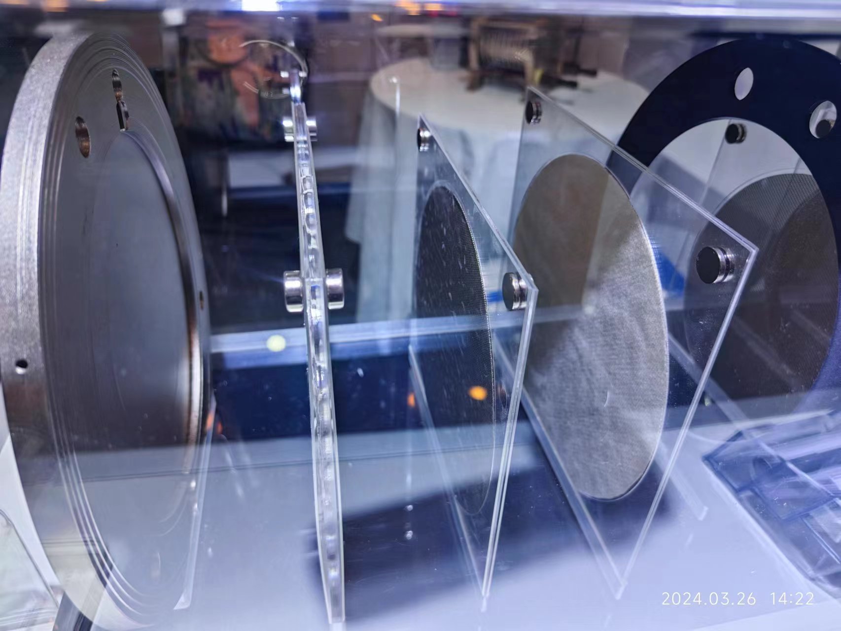
The technology can be used to coat membranes, porous transport layers, gas diffusion layers, mesh electrodes and other electrolyzer components. Fine droplets and controlled spray movement help produce uniform catalyst layers while reducing overspray and expensive catalyst waste.
Electrolyzer Coating Challenges
Electrolyzer catalyst inks may contain precious-metal catalysts, ionomers, solvents and other functional materials. Their properties can make conventional coating processes difficult to control.
Typical challenges include:
- Non-uniform catalyst distribution
- Agglomeration or settling of particles
- Inconsistent catalyst loading
- Poor coating coverage on porous or textured substrates
- Excessive overspray and catalyst waste
- Local flooding, cracking or pinhole formation
- Difficulty scaling a laboratory process to larger substrates
A stable coating process must balance ink formulation, atomization, flow rate, substrate movement, drying conditions and the required catalyst loading.
How Ultrasonic Spray Coating Works
The coating liquid is delivered to an ultrasonic spray nozzle at a precisely controlled flow rate. High-frequency vibration at the nozzle tip breaks the liquid into fine, low-velocity droplets.
The atomized spray is directed toward the substrate using controlled shaping air. A programmable motion system moves the nozzle or substrate to create overlapping spray paths and uniform coverage.
Compared with high-pressure spraying, ultrasonic atomization produces less uncontrolled overspray and offers better utilization of costly catalyst materials. Multiple thin passes can be applied to gradually build the required coating thickness and catalyst loading.
Suitable Electrolyzer Technologies
Ultrasonic spray coating can support coating development for:
- Proton exchange membrane water electrolyzers
- Anion exchange membrane water electrolyzers
- Alkaline water electrolyzers
- Laboratory electrolyzer cells
- Electrolyzer catalyst screening
- Pilot-scale hydrogen production projects
The nozzle, liquid delivery system and motion platform can be selected according to the catalyst ink, substrate dimensions, coating area and production requirements.
Coatable Components and Substrates
Typical coating targets include:
- Proton exchange membranes
- Anion exchange membranes
- Catalyst-coated membranes
- Porous transport layers
- Gas diffusion layers
- Gas diffusion electrodes
- Titanium mesh and porous titanium
- Nickel mesh and nickel foam
- Metal plates and porous metal substrates
- Laboratory test coupons
Direct coating onto a membrane, porous layer or electrode substrate can be evaluated according to the required electrode structure and manufacturing process.
Key Benefits
- Fine and uniform droplet generation
- Precise catalyst-loading control
- Reduced overspray and catalyst waste
- Uniform coverage over flat, porous and textured substrates
- Suitable for low-flow catalyst inks
- Repeatable multi-pass coating
- Programmable coating paths and spray areas
- Compatible with heated substrates and controlled drying
- Scalable from laboratory testing to automated production
- Customizable for different electrolyzer components
Typical Coating Process
A typical electrolyzer electrode coating process includes:
- Prepare and mix the catalyst ink.
- Filter or disperse the ink when required.
- Fix the membrane, PTL, mesh or electrode substrate on the coating platform.
- Set the liquid flow rate, nozzle power, spray width and nozzle distance.
- Program the coating area, movement speed and spray path.
- Apply multiple thin coating passes.
- Control the substrate temperature and inter-pass drying.
- Dry or heat-treat the coated component according to the process requirements.
- Measure coating weight, catalyst loading and surface uniformity.
Final parameters should be established through sample testing because ink properties and substrate structures vary between applications.
Important Process Parameters
The coating result is influenced by:
- Catalyst ink viscosity
- Solid content and particle size
- Solvent composition
- Ink stability and dispersion
- Liquid flow rate
- Ultrasonic nozzle frequency and power
- Shaping-air pressure
- Nozzle-to-substrate distance
- Nozzle movement speed
- Spray-path overlap
- Number of coating passes
- Substrate temperature
- Drying conditions
- Target catalyst loading
These parameters are optimized together rather than adjusted independently.
Recommended System Configuration
A typical ultrasonic coating system for electrolyzer electrodes may include:
- Ultrasonic spray nozzle
- Digital ultrasonic generator
- Precision syringe pump or pressure-based liquid delivery system
- Programmable XY or XYZ motion platform
- Adjustable shaping-air module
- Heated substrate platform
- Exhaust or fume-extraction enclosure
- Catalyst ink stirring or circulation system
- Automatic nozzle-cleaning function
- Vision alignment or substrate-positioning system
Laboratory systems are suitable for material screening and process development. Larger automated platforms can be configured for pilot production and industrial manufacturing.
Sample Testing Is Recommended
Catalyst inks, membranes and porous substrates behave differently during atomization, wetting and drying. Sample testing is therefore recommended before final system selection.
For evaluation, please provide:
- Catalyst ink composition
- Solvent type
- Solid content
- Viscosity
- Particle size
- Target catalyst loading
- Substrate material and dimensions
- Required coating area
- Laboratory or production capacity
- Photos or drawings of the component
Based on this information, FUNSONIC can recommend a suitable nozzle, liquid delivery method, motion platform and drying configuration.
Frequently Asked Questions
Can ultrasonic spray coating be used for PEM electrolyzer electrodes?
Yes. It can be used to deposit catalyst inks onto membranes, porous transport layers and other PEM electrolyzer components. The final process depends on the ink formulation, substrate and target catalyst loading.
Is the process suitable for AEM and alkaline electrolyzers?
Yes. Ultrasonic spray coating can also be evaluated for AEM components, nickel mesh, nickel foam and other substrates used in alkaline electrolyzer systems.
Can the system coat porous or mesh substrates?
Yes. Controlled fine droplets and shaping air can improve coating distribution over porous, mesh and textured surfaces. Sample testing is recommended to optimize penetration and surface coverage.
How is catalyst loading controlled?
Catalyst loading is controlled through the ink concentration, liquid flow rate, coating area, nozzle movement speed and number of passes. The coated component should be weighed or otherwise measured during process development.
Can the catalyst ink be kept mixed during coating?
Yes. Stirring, circulation or another suitable ink-management method can be added when particles tend to settle or agglomerate.
Can the process be scaled from laboratory testing to production?
Yes. The process can begin with a laboratory coating platform and later be transferred to a larger automated system. Key parameters should be documented during development to support scale-up.
Discuss Your Electrolyzer Coating Project
Tell us about your catalyst ink, substrate, coating dimensions and target catalyst loading. FUNSONIC can provide sample testing and recommend an ultrasonic spray coating configuration for your electrolyzer application.