
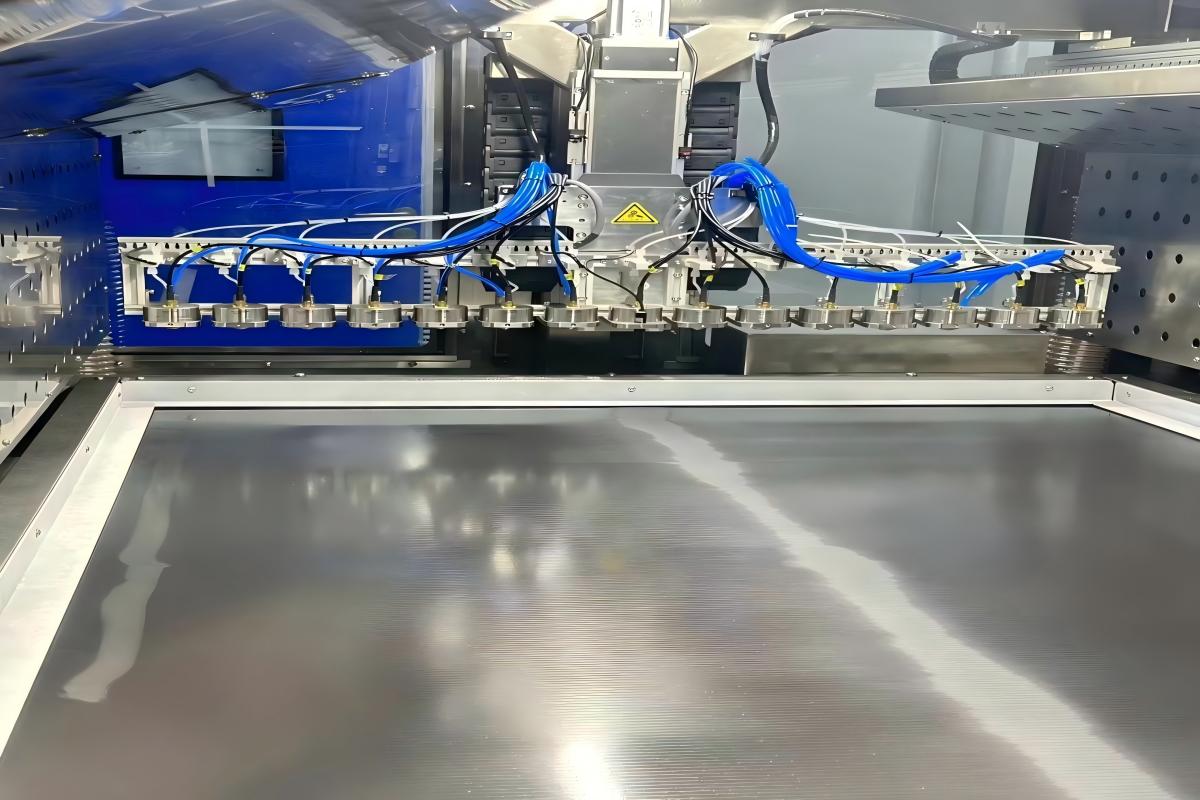
The uniformity of the catalyst layer (CL) in a fuel cell membrane electrode assembly (MEA) directly determines the initial performance, durability, and localized degradation behavior of the fuel cell stack, including issues such as hotspot formation.
The key factors affecting catalyst layer uniformity can be divided into four major categories: ink formulation and physical properties, coating process parameters, drying and substrate conditions, and environmental control and online monitoring.
1. Ink Formulation and Physical Properties
Particle Size (D90) Particle size directly affects ink dispersion stability and coating defects. Excessively large particles (for example, >1 μm) may cause nozzle clogging during spraying and increase coating pinhole defects (>2%). An ideal particle size below 300 nm helps achieve uniform coating and maintain a pinhole rate below 0.1%.
Ink Viscosity and Rheology Ink viscosity strongly influences spreading behavior on the substrate. Excessively high viscosity may cause uneven coating or stringing, while excessively low viscosity may lead to flow instability and coffee-ring effects. The viscosity must be optimized according to the selected coating method.
Solid Content and Dispersion Stability Solid content affects catalyst loading uniformity. The ink should maintain excellent dispersion stability through processes such as ultrasonic dispersion or homogenization, with low sedimentation rate (<5%) to achieve consistent batch-to-batch loading variation within ±2%.
2. Coating Process Parameters
Coating Thickness and Thickness Variation Thickness variation directly affects local current density distribution. Increasing thickness deviation from ±2 μm to ±5 μm may significantly increase current density variation and the risk of hotspot formation. Precise control of coating head gap and positioning accuracy (such as ±1 μm for slot-die or micro-gravure coating) is required.
Coating Speed and Scanning Strategy Coating speed must be matched with ink flow rate. Excessive speed may cause insufficient deposition, while excessively slow speed may create over-thick areas. Scanning patterns and overlap ratios (30%-70%) should be optimized to eliminate striping effects and improve lateral uniformity.
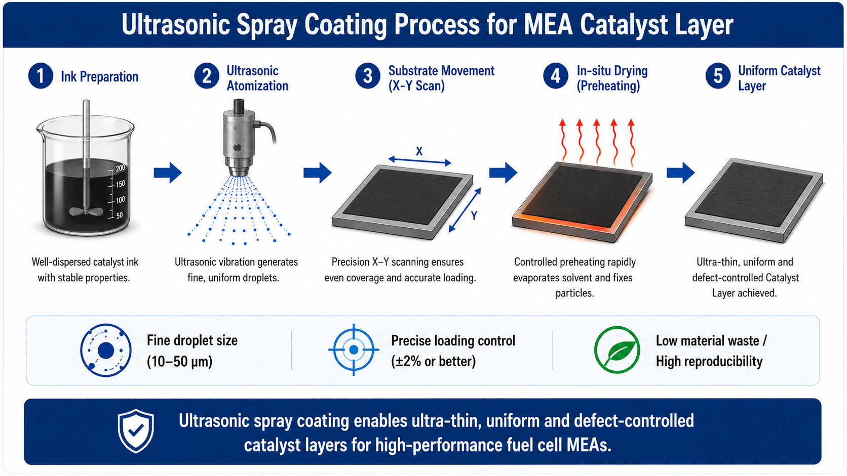
Ultrasonic Spray Coating Parameters For ultrasonic spray coating, important parameters include ultrasonic frequency, spray height, substrate movement speed, and ink flow rate. Higher frequencies, such as 120 kHz, generate finer droplets and improve coating uniformity. Low-flow, multi-pass thin-layer deposition is often preferred for precise catalyst layer fabrication.
3. Drying and Substrate Conditions
Substrate Temperature (Preheating) Moderate substrate heating (for example, 40-80°C) accelerates solvent evaporation, suppresses droplet migration and coffee-ring effects, and helps rapidly fix catalyst particles on the substrate surface.
Drying Temperature Profile The drying process should match solvent evaporation characteristics. A staged temperature profile, such as 60°C for solvent evaporation followed by 80°C for film formation, helps avoid rapid ionomer encapsulation of catalyst particles or excessive coating flow.
4. Environmental Control and Online Monitoring
Ambient Temperature and Humidity Stable temperature and humidity conditions are required because environmental fluctuations can change solvent evaporation behavior and affect coating repeatability.
Online Thickness and Areal Density Monitoring Full-area coating inspection using methods such as X-ray fluorescence (XRF) thickness measurement or photothermal measurement enables real-time monitoring of thickness deviation and catalyst loading variation, allowing timely process adjustment.
Conclusion All parameters must be optimized together. For example, high-frequency atomization combined with substrate heating, and low-flow multi-pass coating strategies, can help achieve highly uniform catalyst layers with ultra-low platinum loading.